

Introduction: Chase the Expandable Robot 1.0


I have always been fascinated by robots, so I decided to participate in the robotics contest and build Chase. Chase is a remarkable and original Arduino robot that can have many capabilities. In this Instructables, I will guide you through the steps of making your own Chase.
Chase is a 3d printed modular robot that can be extended by using magnets and copper tape (I will explain more about that later) to attach different extensions. The magnets and copper tape enable you to customize the robot according to your needs and preferences with a lower cost than buying a new robot. With this feature, Chase can switch between extensions easily and quickly. Extensions allow you to modify the robot's functionality and appearance by snapping on the extension and programming the Arduino nano. Later, I will show you how to create an extension and give you the program for it.
Supplies
Here is a list of what you will need and where to get them:
Tools
- 3d printer
- Screwdriver for small screws (Phillips head)
- Wire cutters
- Wire strippers
- Computer with the Arduino IDE Installed
- Slicer software
- Super glue or glue gun
- soldering iron (optional)
Supplies for the robot(not including extension)
- Arduino nano + cord (Arduino nano with old bootloader)
- DIY USB male power supply cable
- Breadboard
- Breadboard wires (highly recommended but needed) here with breadboard
- 2 360degree micro servos
- 6mm Copper tape
- 2 ball bearings
- Electrical tape
- 6 6*3 neodymium magnets
- Infrared remote control + IR receiver
- VANYUST Mini power bank
- 60 Lego treads
- Numerous jumper wires
- 8 M2*16 Self Tapping Phillips Screws
- Filament (filament I used)
- One led light
- One 100 Ohm resistor
- Any on/off switch
- Heat shrink tubing(optional)
These are the cheapest components that I could find and will definitely fulfill the needs of the robot and expect to have extras. If you find a cheaper solution, feel free to share it.
Step 1: Print the Pieces


First of all, you'll need a 3D printer. If you don't have one, you can borrow one from a friend, a library, or a maker space. Or you can buy one online for as low as $200. Next, you'll need to download these stl. files below. Afterwards, you'll need the 3D printing software. This is the program that will turn your digital designs into instructions for your printer. You can use free software like Cura, Slic3r, or PrusaSlicer. To ensure that your 3d print works well, make sure the 3D printer has supports enabled for overhangs and bridges. Supports are additional structures that help hold up the parts of the model that would otherwise sag or collapse. You can remove the supports after the print is done, either by snapping them off or using a tool like a knife or pliers.
Chase robot 1.0
Attachments


Step 2: Preparation


Gears Assembly:
- Apply a small strip of electrical tape (approximately 5mm wide) to both sides of the ball bearings and trim any excess tape. This will ensure a snug fit for the ball bearings within the gears, while also allowing for their potential reuse in future projects such as Chase2.0. If a permanent solution is preferred, superglue may be used instead.
- Insert the ball bearings into the appropriate holes in the gears.
Copper Tape Wires:
- Cut a jumper wire, leaving one side stripped and the other side with a male pin.
- Cut a strip of copper tape, leaving the paper backing intact.
- Place the stripped wire onto the copper tape and secure it with electrical tape, ensuring a solid connection.
- Repeat these steps until you have a total of wires.
USB to Pin Wire (Using DIY USB Male Power Supply Cable):
- Remove the outer rubber casing from the USB cord as shown in the reference image.
- Cut and strip two jumper wires. One should have a male end for the breadboard, and the other can have either a male or female end.
- Connect the jumper wires to the corresponding wires of the USB cord (not red to black), and secure them with electrical tape. Alternatively, soldering or heat shrink tubing can be used for a more durable connection.
USB to Pin Wire (Using Regular USB Cord):
- Remove the outer rubber casing from the USB cord as shown in the reference image.
- Carefully strip the red and black wires of the USB cord.
- Insulate the green and white wires with electrical tape.
- Follow steps 2 and 3 from the previous section (USB to Pin Wire Using DIY USB Male Power Supply Cable).
Switch Assembly:
- Cut and strip two jumper wires. One should have a male pin for the breadboard, and the other will connect to one of the ends of the USB to pin wires.
- Connect the stripped ends of the wires to the switch and secure them with electrical tape or heat shrink tubing.
Gear Servo Assembly:
- Attach the servo arm to the micro servo using the provided screw.
- Connect the gear to the servo arm.
- Remove the stickers from the micro servo.
- (Optional) Secure the back of the servo arms to the gear using the additional screws provided with the servo.
- Repeat these steps for the second micro servo.
Step 3: Programming

The following code is the core of Chase's functionality. It consists of four main parts:
- Libraries: The code imports two libraries: IRremote.h, which handles the input from the IR remote, and Servo.h, which controls the servos that move the treads and the LED.
- Variables: The code defines several variables to store the robot's state, such as the tread speed, the LED state, and the last remote button pressed.
- Setup: The code initializes the servos and attaches them to their pins. It also enables the IR receiver to listen for signals from the remote.
- Loop: The code runs in a loop that checks for signals from the remote. Depending on the signal value, it sets the tread direction and speed. If no signal is received for a certain amount of time, it stops the treads.
- Reset and Execute: The code has two custom functions: reset(), which stops the treads, and execute(), which updates the servo positions and toggles the LED state every 500 milliseconds to prevent the battery from shutting off.
This is a brief overview of the code. For more details, please ask me in the comments section.
To use this code, download it and upload it to your Arduino nano.
This is the programming for Chase.
#include <IRremote.h>     //library for the IRremote
#include <Servo.h>        //library for the servos

const int RECV_PIN = 3; //the IR receiver pin
const int ledPin = LED_BUILTIN;
int led_state = LOW;
int right_treads=0;//controls the right treads of the robot
int left_treads=0;//controls the left treads of the robot
int speed=0;//the current speed of the treads of the robot
int set_speed=75;//the set speed of the treads of the robot


unsigned long timeout = 0;
unsigned long lastSignalTime = 0;
const unsigned long TIMEOUT_THRESHOLD =200;

Servo rservo;//naming a servo
Servo lservo;
String ButtonPressed; //a variable which is determined by the button pressed on the IR remote
IRrecv irrecv(RECV_PIN); // Create an IRrecv object
decode_results results; // Create a decode_results object

void setup() {
  lservo.attach(5);//sets the pin number for the servo
  rservo.attach(6);
  lservo.write(90);//tells the servo to stop
  rservo.write(90);


  Serial.begin(9600);//begins the serial monitor
  irrecv.enableIRIn();//a function that prepares the Ir sensor


  pinMode(ledPin, OUTPUT);


}


void loop() {
  if (irrecv.decode(&results)) {
    if (String(results.value, HEX) != "ffffffff"){ButtonPressed=String(results.value,HEX);}

//These control what happens depending on the button pushed on the remote
//to control left_treads/right_treads make it equal "1" or "-1",  1=clockwise  -1=counter-clockwise
    if(ButtonPressed=="ffa25d"){}
    if(ButtonPressed=="ff629d"){left_treads=-1;right_treads=1;}
    if(ButtonPressed=="ffe21d"){}
    if(ButtonPressed=="ff22dd"){left_treads=1;right_treads=1;}
    if(ButtonPressed=="ff02fd"){}
    if(ButtonPressed=="ffc23d"){left_treads=-1;right_treads=-1;}
    if(ButtonPressed=="ffe01f"){}
    if(ButtonPressed=="ffa857"){left_treads=1;right_treads=-1;}
    if(ButtonPressed=="ff906f"){}
    if(ButtonPressed=="ff6897"){}
    if(ButtonPressed=="ff9867"){}
    if(ButtonPressed=="ffb04f"){}
    if(ButtonPressed=="ff18e7"){}
    if(ButtonPressed=="ff7a85"){}
    if(ButtonPressed=="ff10ef"){}
    if(ButtonPressed=="ff38c7"){}
    if(ButtonPressed=="ff5aa5"){}
    if(ButtonPressed=="ff4ab5"){}
    irrecv.resume();//prepares Ir sensor for new results
    lastSignalTime = millis();
  }
  timeout = millis() - lastSignalTime;
  //Serial.println (left_treads);


  execute();


  if (timeout > TIMEOUT_THRESHOLD) {
    reset();
  }
  else{
    speed = set_speed;
    }
}


void reset(){
  //ButtonPressed="0";
  left_treads=0;
  right_treads=0;
}

void execute(){


  lservo.write(90-(left_treads*(speed)));
  rservo.write(90-(right_treads*(speed)));
  Serial.println (ButtonPressed);
  if (millis()%500==0){if (led_state==LOW){led_state=HIGH;}else{led_state=LOW;}}
  digitalWrite(ledPin,led_state);
}

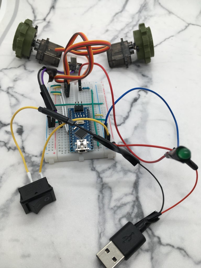
Step 4: Wiring

The diagram above illustrates the circuitry of Chase. The components are connected as follows:
- The IR receiver module is attached to the digital pin D3 of the Arduino board.
- The left micro servo motor is attached to the digital pin D5 of the Arduino board.
- The right micro servo motor is attached to the digital pin D6 of the Arduino board.
- The LED is connected to a resistor, which is connected to the digital pin D13 of the Arduino board.
When you finished the wiring, the next step is to build!
Step 5: Build

To assemble the robot, you need to follow these steps.
First prepare the bottom piece of Chase by inserting the components into the designated spot but unplug the IR receiver for now.Then, set it aside for later.

Next, insert a strand of filament into the robot where the flap fits into. This will be a hinge to open and close the flap. When the filament is in, then cut the extra filament and glue it or melt it with a soldering iron to keep it from coming out of the top piece.

Next, gather eight of the copper tape wires and find the end with the copper tape. Insert those ends of the wires into the 8 middle holes of the top piece. Finally, peel off the backing of the copper tape and press it firmly onto the top piece making sure it is adhered to the top piece.

The next step you will need to insert the neodymium magnets into the holes of the robot's body. To do this apply some superglue around the edges of the magnet and press it firmly against the holes of the robot, there should be 6 holes(five of them are on the top piece and one on the flap). Hold it for a few seconds until the glue sets.IMPORTANT -make sure the front magnets of the top piece are facing the opposite direction than the back magnets.This will ensure that the magnet stays in place and does not fall off or move around. Repeat this process for the other holes and magnets.

The next step is to connect the copper tape wires to the breadboard. You need to insert the pin side into the holes on the breadboard that correspond to the circuit diagram. The picture below illustrates how to do this correctly. Make sure the wires are firmly attached and do not touch each other.

Next, you will need to place the IR receiver into the slot in the front of the robot.Then plug IR receiver back to the Arduino nano.

Then place the top piece onto the bottom piece and place the sides on and screw them in.

Last of all, put the ball bearing gears to the sides of the robot and add the treads.

Now your done!
Step 6: Extension


Supplies For Extension
- Four of the neodymium magnets
- Filament
- Supplies for at least 2 copper tape wires
- led
- resistor
*All these supplies will be the same materials as the ones for building Chase
Build
1.Print the pieces.
2.Glue magnets into the holes of the bottom piece and make sure to have the front magnets facing a different direction than the back
3.Follow the wiring below in the picture

4.Insert the led into the hole and the hole in the top and insert the top into the larger holes of the bottom piece for the extension.
5.Glue it with super glue.
6.You're finished!
If you need the program with the extension you can find it below or in the program section.
Tank extension for Chase 1.0
Step 7: Conclusion
This was an awesome project to make and i hope you liked Chase also. Since this is Chase 1.0, please keep an eye out for my next version 2.0 . If you have any questions, I would love to answer them to the best of my ability. This was so far the coolest robots I have and is my first ones I designed so wait for 2.0 to arrive to have a better experience with Chase as I will update and make him better. This is an original idea that i had and would love to hear your ideas for 2.0.
I would like to thank Paul McWhorter on YouTube since his video helped me a little bit for the IR receiver for my program.This was a fun experience and i hope you liked it too.

Runner Up in the
Robotics Contest


2 Comments
18 days ago
Really well done and documented - thanks for sharing :D
Reply 18 days ago
Thanks I really appreciate it.This is my first robot I designed and didn’t have the most experience with arduino but I learned and had fun at the same time :D .I worked really hard on this, so it means a lot to me.