

Introduction: Create Your Own NanoLeaf LED Panels!


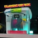


For today's project, we are going to create a NanoLeaf LED panel
The problem!
We all know that NanoLeaf LED panels are quite expensive; they cost around 12,000 PHP or 214 USD. However, you can create today's project at a very affordable price.
VIDEO TUTORIAL:
Supplies


Let's start with the things you will need: a 12V power supply, a perfboard, an ESP8266 Wemos D1, 3 meters of WS2811 LED strips (enough to create 8 panels), a Mini 360 DC-to-DC buck converter, a DC power jack connector, 9 pieces of male 3-pin JST connector, 8 pieces of female 3-pin JST connector, solid wire, no more nails adhesive, and a 3D printer to print the panels.
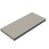
Step 1: 3D Printing the NanoLeaf


The first thing we need to do is to print this beautiful 3D model of NanoLeaf from our generous friend on Thingiverse! I printed the base in black PLA, and for the cover, I printed it in white PLA to act as a diffuser.
Thingiverse Link: (https://bit.ly/49oZvaS)
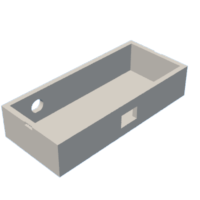
Step 2: Putting the LED Strip Inside the Bases


After completing that step, it's time to place the LED strip inside the bases. We need approximately 35 cm in length to wrap around the interior of one base.
Step 3: Soldering Time


After placing the LED strip inside the bases, it's time to solder the male and female wire connectors onto the LED strip. Pay attention to attaching the female connector to the incoming side of the LED, as indicated by a small arrow printed along the strip, and connect the male connector to the outgoing side of the LED. Be sure not to reverse this connection, as doing so could damage the LED or other electronic components. In my case, I've connected the red wire to the 12v, the black wire to the GND, and the yellow wire to the DIN connection.
Repeat this process for the remaining bases.
Step 4: Setting Up the Brain and the Electronics


Now, it's time to set up the brain and the electronics. The first thing we need to do is set up the ESP8266. To do this, simply connect it to your computer using a USB cable and navigate to the web address install.wled.me using your web browser.
Click the "install" button, then choose your board. In my case, it is COM13. After that, click "connect." Once connected, click "install WLED" and proceed with the installation. Let it complete its process. Once the installation is done, click "next" and connect it to your Wi-Fi network.
Once the device is connected to the network, you can click "visit device" to access your GUI and find the IP address of your device.
WLED Link: (install.wled.me)
Step 5: Putting the Electronics in the Perfboard


Now, it's time to place all the electronics on the perfboard. We'll start with the ESP8266, followed by the female socket connector, and lastly, the mini 360 DC to DC buck converter.
Using a solid wire, we will use it as a pathway for our connections. For now, we will only attach a solid wire to the positive and negative connections of the socket connector leading to the mini 360 buck converter. We need to adjust the output of the buck converter to just slightly above 5v before connecting it to the ESP8266.
To do this, we need to use a multimeter and attach the alligator clip to the output of the mini 360 buck converter. Now, it's time to turn the potentiometer with a small screwdriver until the reading is just slightly above 5v.
Next, it's time to connect the output of the buck converter to the ESP8266. Additionally, I use a male 3 Pin JST connector from the ESP8266 to connect to the LED panels. The black wire is connected to the GND, and the yellow wire is connected to GPIO 12 of the ESP8266.
Once it's done, I place the perfboard inside the 3D-printed case.
Step 6: Wall Hanging


Next, it's time to hang these LED panels on the wall. The first thing I did was to use my meter to find the center of the wall and then mark it with a pencil. After that, I put on gloves because I am going to use a "no more nails" adhesive. Once this adhesive gets on your hands, it's somewhat difficult to remove, so I recommend wearing gloves when using it. Using the "no more nails" adhesive, I glued the panels and the case of the electronics one by one to the wall.
After completing that, I connected each end of the LED strip, and then I closed the base with its cover. This time, we need to power it up with the 12V power supply.
Step 7: WLED - Software Configuration


Now, you need to download the WLED app on your phone and open it. Click the plus button, and then select 'Discover Lights.' Once your LED is found, click the check button. Click 'Configuration,' and then choose 'LED Preferences.' The LED count should be the number of bases you have multiplied by 7. In my case, it's 56. Set the maximum current to 3000 mA. Next, under the hardware setup, change the LED color order to BRG and change the GPIO to 12, because I connected my LED to pin to the GPIO 12 of the ESP8266. Save your settings by clicking this button. You can then verify that all your settings are correct by returning to the main page and cycling through the three primary colors: red, blue, and green.
Step 8: Quick Crash Course


There are a lot of great guides on how to use WLED, so I will not go into a lot of detail in this tutorial. However, I won't leave you without a quick crash course in the basics. On the main screen, you'll find a brightness slider located at the top-right of the screen. This serves as the master brightness control and can be accessed from any tab.
There are four main pages that can be accessed from the four main tabs at the bottom of the screen: Colors, Effects, Segments, and Presets. However, I will only discuss the Colors and Effects tabs.
Colours Tab
You can basically change the color of your NanoLeaf in this tab.
Effects Tab
Here, from the name of the tab itself, this allows you to switch between various dynamic and static animations for the NanoLeaf panels. As you can see, there are lots of effects that you can choose from.
Step 9: Enjoy!


And there you have it, the project is completed! It's time to sit back and enjoy the fruits of your labor.
And as always, keep learning and have fun! Bye!


2 Comments
Question 4 weeks ago on Step 9
I understand why there is no part with no leds, any idea how to fix that?
Answer 4 weeks ago
Hello!
If you're referring to the section without an LED, it's intentional in my design. However, you can opt for a full LED setup. I cut my RGB strip into 35 cm lengths, but for a complete LED experience, cut yours into 36 cm. 😃