
Introduction: 3D Printed Adaptive Game Joystick and Button
I came up with the Adaptive Game Joystick because there weren't many affordable controllers for individuals with disabilities. The goal here is to make gaming inclusive and easy for everyone. I think replicating these controllers could be a simple and cost-effective fix for this issue.
There are two main parts in play: the joystick and the button. You can use them together, and if you want, throw in a couple of each. We're mostly doing 3D printing because it's cheap and straightforward for making all these complex parts. The joystick has interchangeable heads, so just pick the one that suits you best. Just a heads up, though – don't go too rough with the joystick; it could break the heads, so a bit of caution is in order. The project's still a work in progress, and I'd love to hear any feedback. Check out those notes at the end of each step – they've got some useful tips and important info on putting things together. Thanks and enjoy!
Supplies
Materials:
- 3D printer access and filament (files attached)
- Makey Makey
- Mini USB cable (adaptor if needed)
- 2x alligator clips (included with MakeyMakey)
- Wire
- Conductive tape (aluminum, copper, etc.)
- Electrical tape
- 6x rubber bands
Tools:
- Scissors or hobby knife
- Hot glue gun
- Wire stripper (optional but recommended)
- Cutting mat (optional but recommended)
Other:
Full
Button
Step 1: Printing the Joystick
- The base and cover can be printed with basic settings. Be sure to print the cover upside down to reduce support usage.
- The rotating shafts should be printed on their side so that the flat part of the circle is on the base.
- The inner shaft should be printed vertically for best results on the threading.
- Two nuts are required to be printed.
- You can optionally print inserts for each conductive pad, but this is not required.
- You can pick which head to print. The same mid-shaft is needed for both of them. The mid-shaft should be printed upside down for best results on the threads. More infill is recommended for the mid-shaft, as it's the most prone to breakage (work in progress).
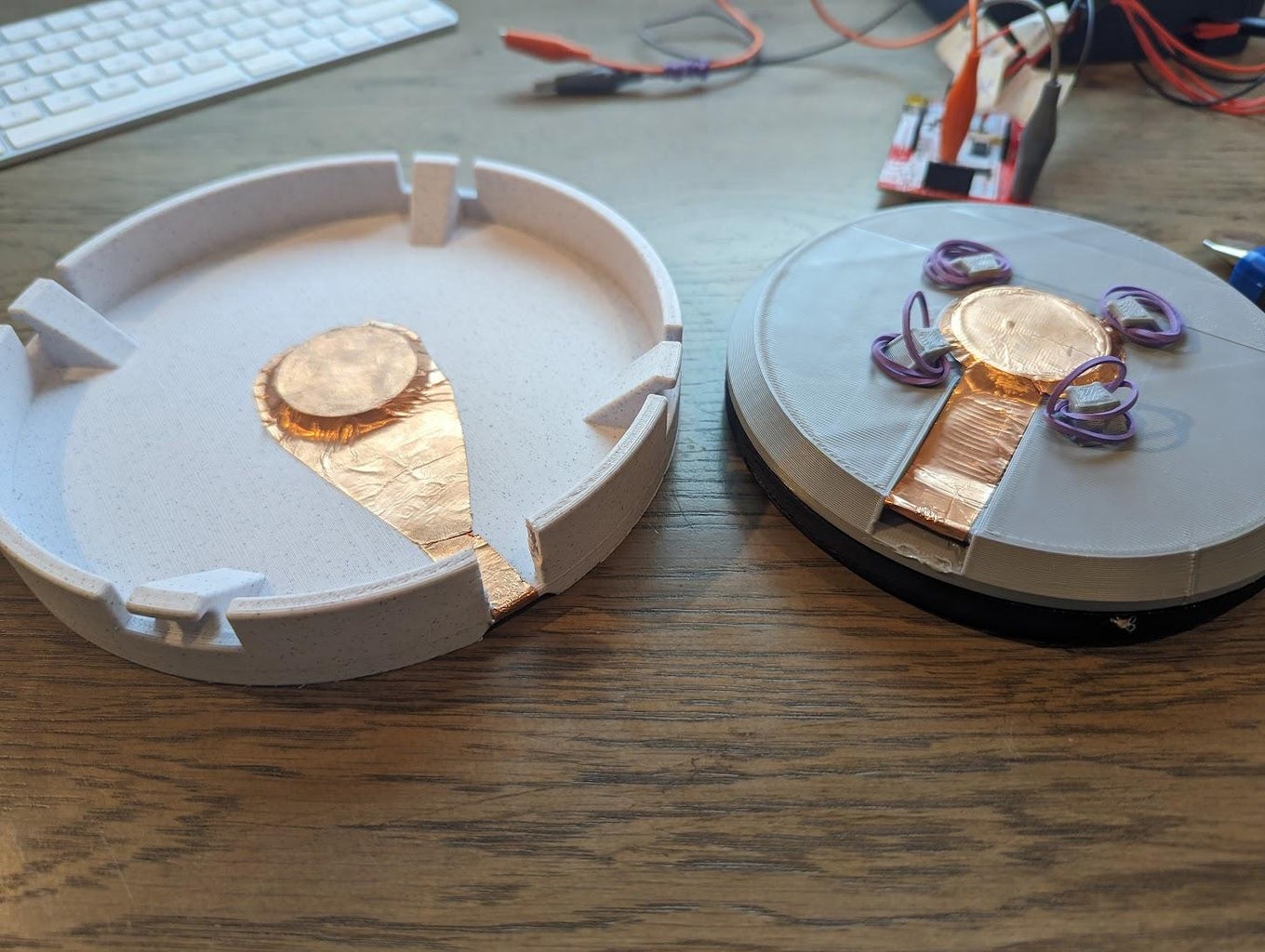
Step 2: Assembling the Joystick Framework
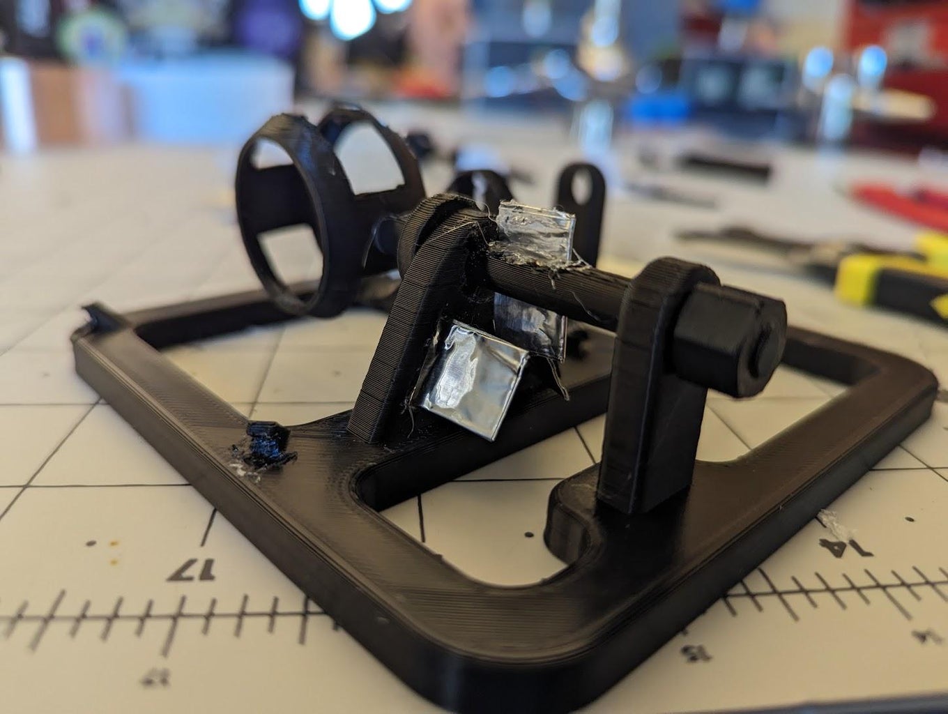
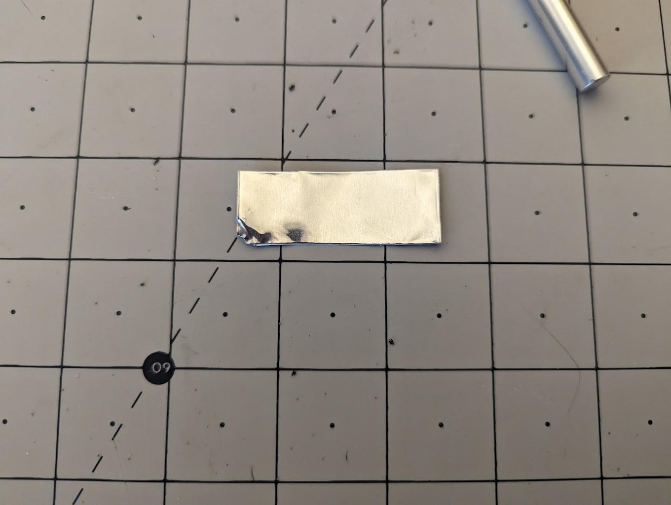
- First, create the electrical pads with conductive tape. They should be approximately 3.5-4 cm long. Cut a strip of tape with this width, and then roll it over itself a few times to make it more sturdy. Next, hot glue the conductive pads into the base only. Do not attach it to the shafts yet, as you won't be able to insert them.
- Next, take the shafts you printed and put them through their respective paths. Insert the large one first, and then the smaller one should pass inside of the first.
- Use the nuts to secure each shaft. They shouldn't be too tight, as the shaft needs to rotate.
- Now you can hot glue the conductive pads into the slits on the shafts. Keep in mind that enough needs to be accessible from the top for wiring.
Step 3: Wiring the Joystick
- First, cut the wires to size. I used black for ground and red for "active," but this is not necessary. You will need 2 ground and 4 "active." I recommend labeling them with tape ahead of time to keep track. Keep in mind that about 10-15 cm will be housed inside the joystick, and another 5-7 cm will be housed in the MakeyMakey housing. If you expect to spread your pieces out more, then more wire should be cut. I recommend at least 25-30 cm, but 40 would be better.
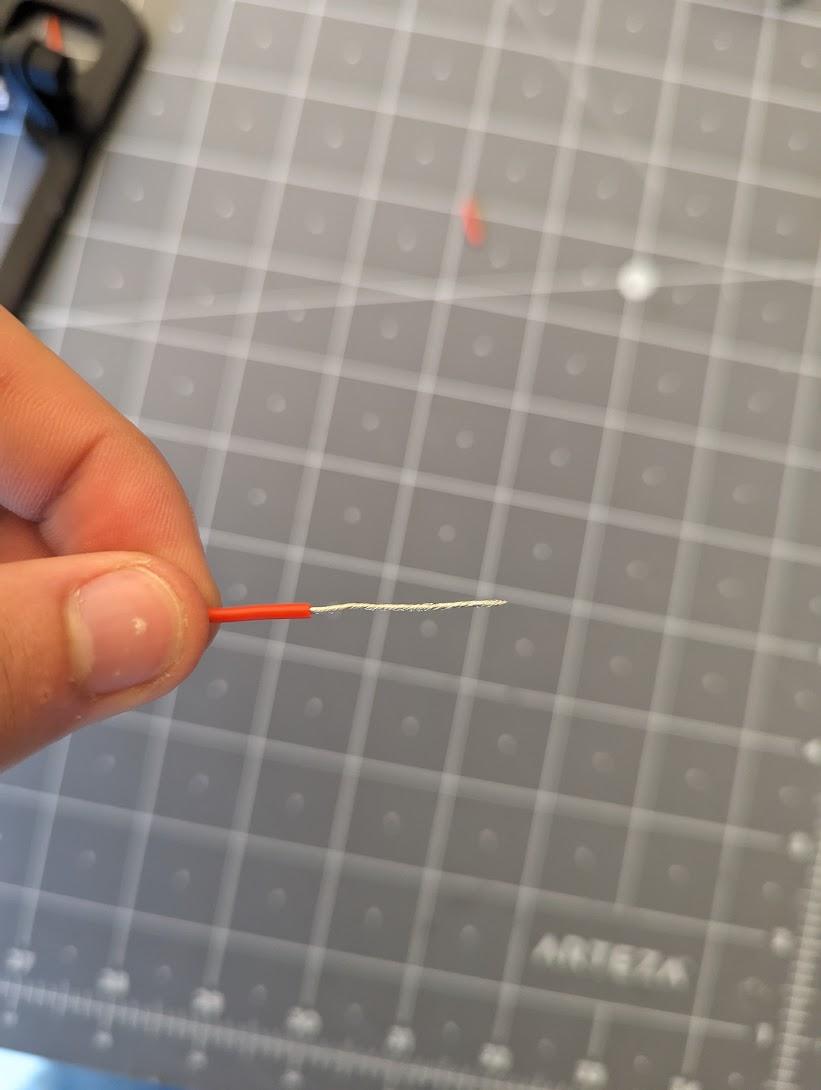
- Next, strip the end of each wire. You can use the wire strippers for this, or, if you don't have them, you can carefully strip the ends with a pair of scissors. After stripping roughly 1-1.5 cm, twist the ends to keep them bound together.
- Be sure that the MakeyMakey is not yet plugged in.
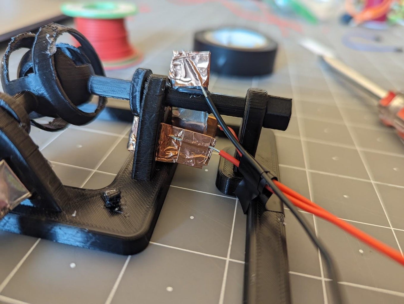
- Next, you will need to cut small pieces of conductive tape. Use this to attach the ground wires first. The ground wires should connect to the pad that runs through the shafts. I recommend first wrapping the wire around the pad and then taping it over with a thin strip of conductive tape.
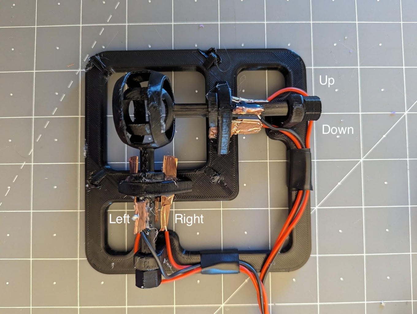
- We will then connect the "active" wires. Refer to the diagram above to connect each wire to the correct pad. You can connect it either on the half of the pad closest to the ground pad or on the half closest to the inner circles where the shafts intersect. Attach it the same as the ground pads.
- Next, use electrical tape to manage the wires. You can tape the wires to the base or just bound them together. It's non-essential, but makes it easier and cleaner when managing the cables. Be sure that the ground pads are able to rotate enough to hit the "active" pads. You can bend the pads a little to make it easier. Don't manage the wires too tightly, as it will be difficult to bend the pads to fit. The managed wires should be able to fit through the arch on the cover.
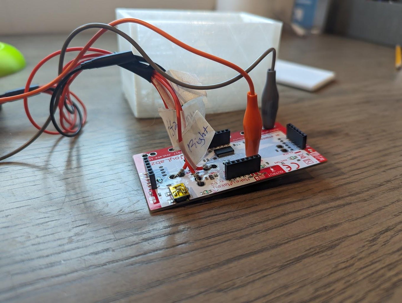
- Lastly, connect the wires to their respective locations on the MakeyMakey. The ground pads should wrap around the holes labeled "ground," and the "active" wires should attach to the arrow keys. Refer to the labeling you did when first cutting the wire to be sure that everything is connected properly.
Step 4: Inserting the Head and Inner Shaft
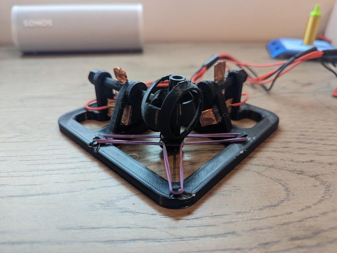
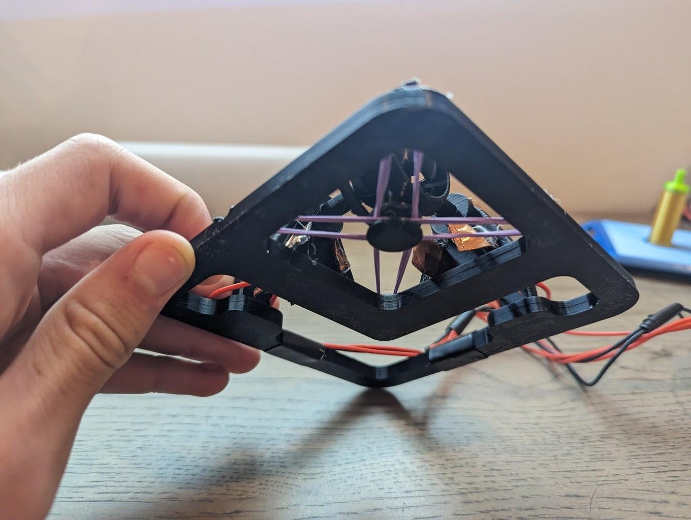
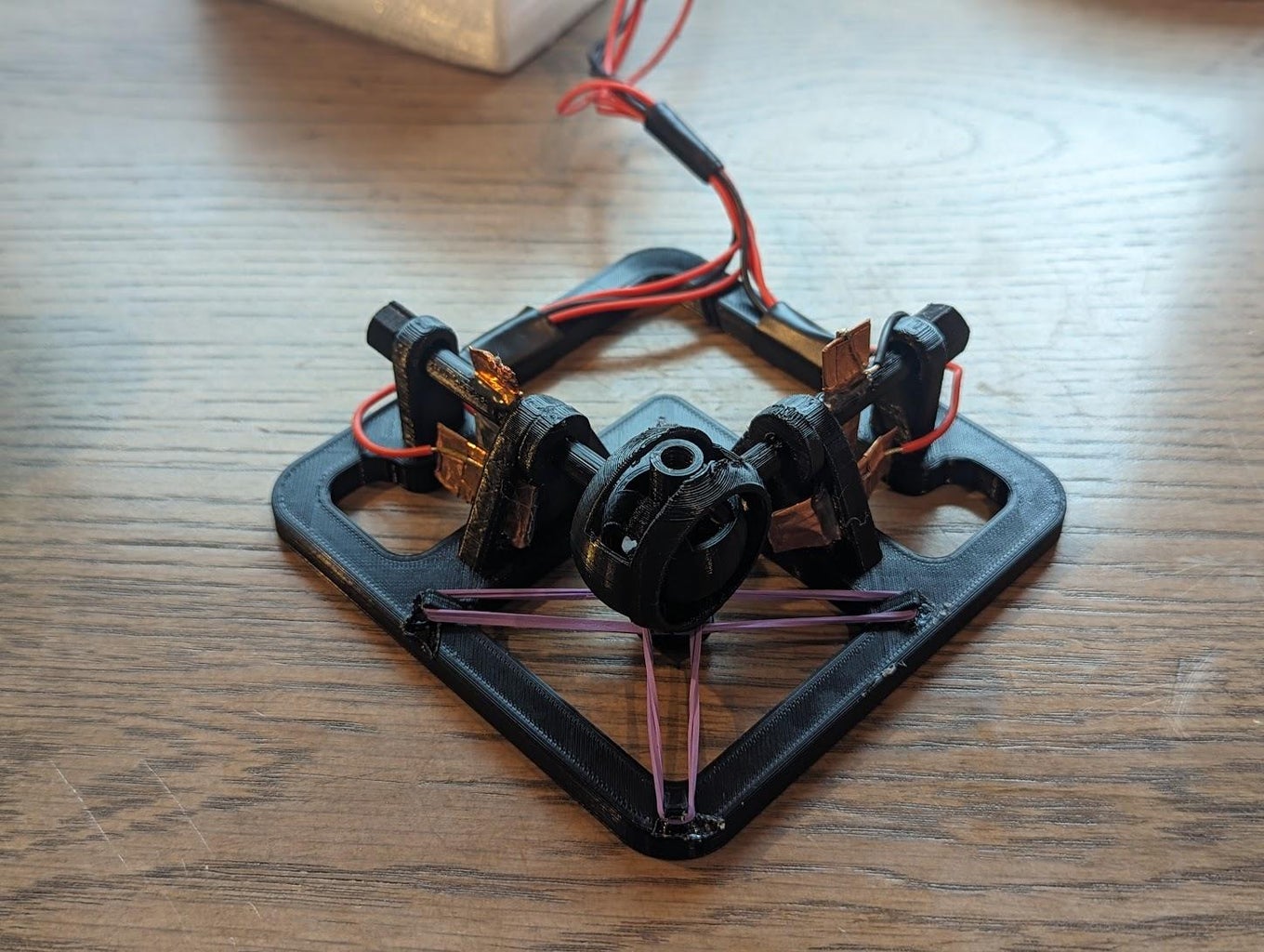
- First, insert the inner shaft upwards through the two spheres. Then use the mid-shaft (without the head attached) to screw in and hold it in place.
- Next, use rubber bands around the corners to allow the joystick to snap back. See the picture above. I used thin rubber bands and double-looped them across the corners, so only two were used.
- You can now remove the mid-shaft. The inner shaft should be somewhat stuck in place. Next, hot glue the mid-shaft to the head of your choosing. You can always print another mid-shaft if you'd like to switch heads in the future.
- Place the cover over the joystick and then screw the head into place. You may have to hold the inner shaft from the bottom to support it while screwing in the head. The joystick is now complete!
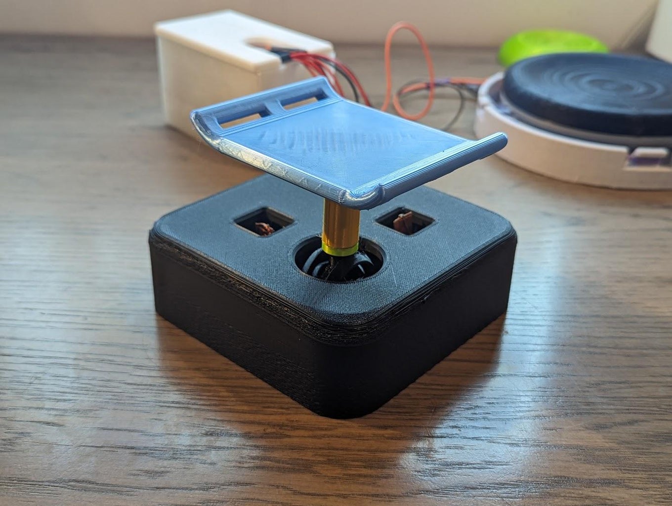
Step 5: Assembling the Button
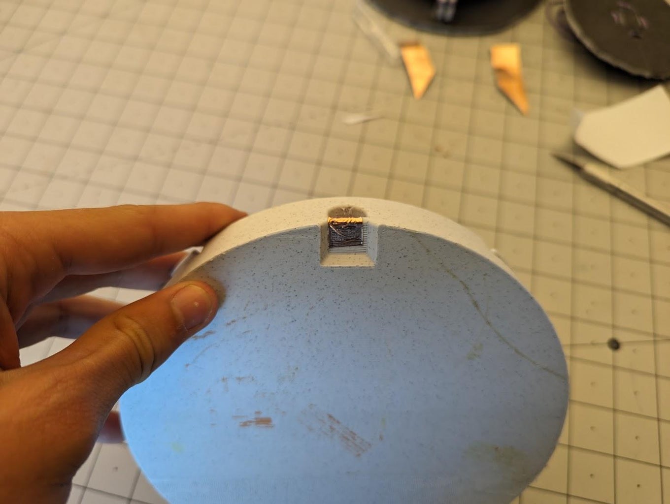
- The button is printed in three parts: the base, the bottom of the head, and the top of the head. Use hot glue to attach the bottom and top pieces of the head. You may print pins to assist in lining up the gluing, but this is not necessary. The orientation of the head does not matter.
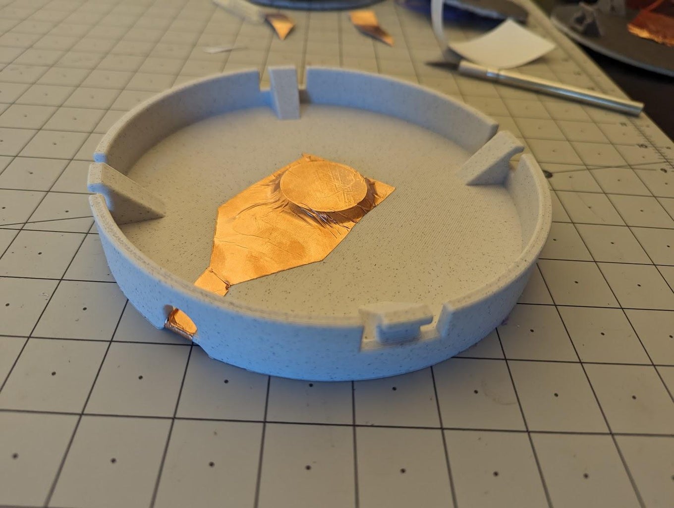
- Next, cut pieces of conductive tape to fit in the channels. Tape them to each piece, tucking the ends in. If there is excess tape, you can use the hobby knife to trim it down.
- Next, we will attach the rubber bands. My rubber bands were thin, so I had to triple-loop them. Hook them around the slots in the head first.
- Next, be sure to orient the head properly. The two pieces of conductive tape should line up with each other. Reach under the head and stretch the rubber bands over the base hooks, as shown in the video.
- Finally, attach the alligator clips to each conductive pad. As I didn't have black, I used grey for ground this time and orange for "active." These alligator clips should then be connected to the MakeyMakey. You can choose which slot to wire the "active" clip to, as there is a space bar option and a left-click option.
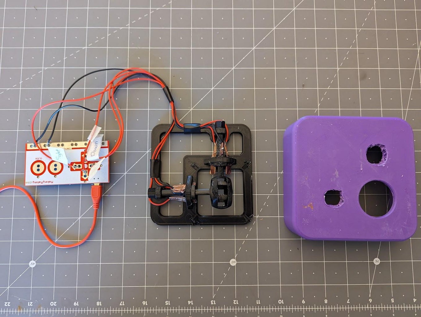
Step 6: MakeyMakey Housing and Connection
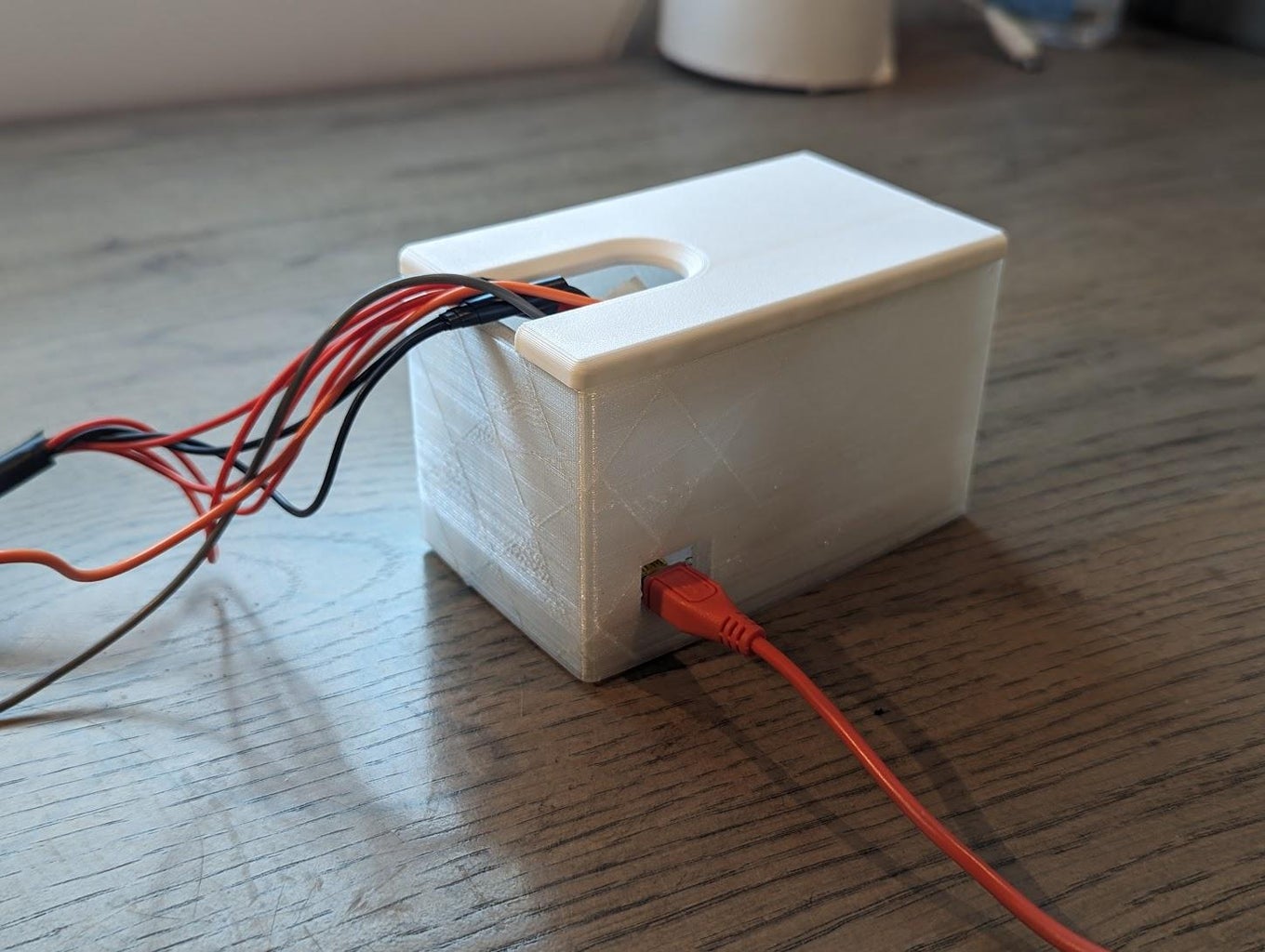
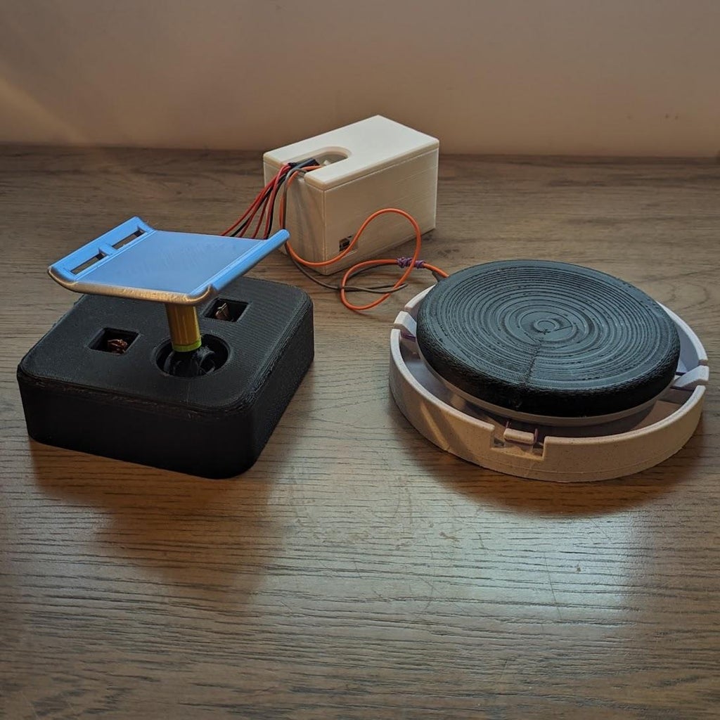
- We can place the MakeyMakey into the housing once the wires are attached. Be sure to orient it so that the Mini USB port is facing the cutout.
- Plug the Mini USB cord into the port, and then plug the other end into your computer (or adapter).
- Route the wires through the hole in the lid, optionally tape the lid, and you're now complete building your joystick and button!
- You can test the inputs using this link. If they're not working at first, you may have to bend the pads in place until you're sure they're making contact.


Comments
2 days ago on Introduction
PRETTY NICE PROJECT